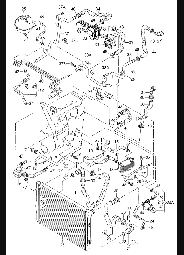
This is a list of the parts of the Volkswagen 2.0 engine.
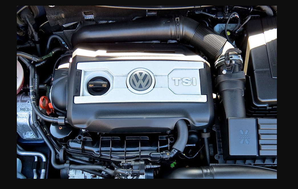
Block
The block is a cast iron, closed deck design with six cylinders. The engine features a wet sump system, meaning that it has a separate oil pan and pump to maintain lubrication to the crankshaft and camshafts. The block also has chain-driven overhead camshafts (OHC) for each cylinder bank.
Crank
The crank is the part of the engine that rotates. It’s connected to the pistons, camshaft, valves and oil pump. The crank has a number of parts that have to be aligned perfectly in order for it to work properly:
- Rod journals – The rod journals are found on both sides of each connecting rod. They allow for smooth rotation as they go through their cycle from top dead center (TDC) to bottom dead center (BDC) while they’re being driven by connecting rods attached to pistons inside cylinders.
- Crankshaft journals or main bearings – These are also found on both sides of each main bearing journal except unlike rod journals they don’t rotate with every revolution but instead stay stationary as their respective crankshaft rotates past them during operation.* Crankpin – This is where one end of your connecting rod attaches itself with a pin bearing so that it can move back and forth smoothly while being driven by its cylinder’s piston; these are also called main bearings because they’re located between two main bearings which are located inside oil sumps.* Main Bearing caps – These serve several purposes including providing support for mainshaft bearings, preventing them from bending under load during operation (which could cause catastrophic damage), as well as allowing access when necessary for service work such as replacing old seals or worn out parts.”
Oil pump – crank driven
The oil pump is driven by the crankshaft and is a single stage positive displacement pump. It has variable displacement mechanism which pushes the oil from the sump to the rocker arms and valve covers. It consumes only about 1/2 horsepower even at maximum load, so it’s quite efficient for its size and power requirement. The whole assembly sits inside of a case that separates it from other engine parts with gaskets, seals, and bearings.
Oil pump – camshaft driven
The oil pump is driven by the camshaft. It is located in the block and has a drive sprocket and a driven sprocket. The timing belt drives the camshaft, which in turn drives the oil pump.
Piston cooling nozzle and oil jet
A piston cooling nozzle is installed in the combustion chamber to cool down the pistons, which helps prevent damage to them. The piston cooling nozzles are made of a material that allows for high-heat transfer and are connected directly to an oil jet. The oil jets come from an oil system that consists of an accumulator, filter, pressure regulator and lubricating pump.
Pistons & con rods
Piston and con rod parts are made from aluminum, for improved strength and weight savings. The pistons have a flat crown shape, which reduces friction between the piston rings and cylinder walls. These castings (pistons) are forged to ensure precise tolerances.
The connecting rods are also forged steel, but they’re lighter than iron rods because they don’t contain any iron in their makeup. They can be made stronger by using powdered metal or through the use of high-strength steels such as titanium alloy.
Cylinder head
The cylinder head is the component of your engine that houses the valves and other components. The valve seat inserts, also known as valve seats, are used to seal against the piston rings when they close. Valve guides help guide each valvetrain component, including pushrods and rocker arms. Valve springs are responsible for keeping pressure on the valves when they are closed in order to ensure a proper seal between the top of each piston and its corresponding cylinder wall. Valve stems seal with oil wipe rings that act as cushioning material between them in order to prevent any damage from occurring when they open or close while still maintaining overall performance of your VW 2.0 engine parts diagram system..
Inlet ports (1)
Inlet ports are the holes in the cylinder head that allow air/fuel mixture to enter into the combustion chamber. The inlet ports can be circular or rectangular and are shaped to allow for maximum flow of fuel and air into their respective chambers.
To accommodate these shapes, the walls of these ports are inclined at an angle. This angle helps guide fuel-air mixture from one side of the port to another before it enters into its respective combustion chamber. It also helps keep any hot gasses that have exited from a previous cycle out of this new cycle’s path as well as directs them away from part of engine block that needs cooling so as not to cause damage by overheating or excessive heat build up during operation (which could lead this area being susceptible).
Baffle plate & rocker shafts (1)
The baffle plate is a cover for the rocker shafts. It has a hole for each of them to provide oil to the valve train. The baffle plate is bolted to the cylinder head and cast in one piece with it.
Rocker shafts (2)
Rocker Shafts
The rocker shafts are the rods that connect the camshaft to the valve rockers. The rocker shafts can be adjusted by loosening a pair of bolts and rotating the shaft until their angles align with those of their respective cam lobes.
Oil supply to inlet valve stems (drip feed) (1)
The oil supply to inlet valve stems (drip feed) is controlled by the camshaft. Oil delivery to the camshaft bearing caps is via a hole machined into each bearing cap.
Oil supply to exhaust valve stems (direct supply) (2)
An oil supply line is connected to the exhaust valve stem. The oil supply line is a flexible tube that has a connector at one end and an opening at the other end.
The opening of the oil supply line can be connected directly to the exhaust valve stem, as shown in Figure 3-1.
Valve stem seals & oil wipe rings (3)
The valve stem seals and oil wipe rings are located in the cylinder head. The valves are connected to their respective camshafts by way of rocker arms that rotate on roller bearings, which ride on the surface of a pair of cam lobes.
When you rotate the engine’s crankshaft 180 degrees, each camshaft rotates twice as fast as it did before (because it is now moving in the opposite direction). As a result, when you’re operating your engine at a given speed (like 4000 RPM), both cams will travel at half that speed (2000 RPM) due to this rotation difference between them.
This results in an uneven wear rate between both sides’ valve stems that causes leaks through either one or both sides’ seal areas; this is why VW 2.0 Engine Parts Diagram recommends replacing all three seals at once rather than just one or two.
Takeaway:
Now that we’ve covered the basics of Volkswagen’s 2.0 engine and how it differs from its 1.8 predecessor, here are some takeaways to keep in mind:
- The compression ratio of a VW 2.0 engine is lower than that of a 1.8 engine, which means less power but better fuel economy.
- The turbocharger on VW 2.0 engines is bigger than that on 1.8s, which means they’re more powerful and faster off the line but lose speed at higher rpms (revolutions per minute) due to turbo lag (the time it takes for exhaust gases to spin up the turbine).
- You can use your VW 2.5 as a carpool vehicle since it has fewer cylinders than other models in its lineup and therefore produces less pollution during travel—and no matter what type of transmission you drive or how much gas mileage you get, having a carpool buddy never hurts!
Conclusion
Well, there you have it! We hope that this VW 2.0 Engine Parts Diagram was helpful in understanding how the engine works. If you have any questions or need more information, please feel free to contact us at anytime.